1. Product introduction
1-1. Overview KSR/SBW Series Three-Phase Numerical Control Intelligent Regulator (Hereinafter referred to as Regulator) is a new-generation intelligent regulator developed by our company with many years’ effort on the basis of our experience in production of the compensatory electricity regulator for years. It adopts the newest DSP computing chip control technique, rapid AC sampling technique, zero-crossing switching technique and fast compensating voltage regulation technology, and combines the functions of intelligent meter, fast voltage stabilizing and fault diagnosis so that it can be safer, more efficient and accurate. It is mainly composed of isolation transformer, SCR voltage stabilizing module, MCU control core +high precision current and voltage sampling component, fast voltage regulation technology and safety protection device. Featured with safety, high efficiency, energy-saving and environmental protection, it is a perfect combination of SCR technique and transformer switch technique without surge current. The product is widely used as a part of the large electromechanical equipment in industry, transportation, post and telecommunication, national defense, railway and scientific research, which require the electrical equipment of high precision and stable voltage.
1-2. Characteristics (1) Intelligent LCD display: Intelligent meter clearly and accurately displays line voltage, phase voltage, current, frequency, temperature and working condition in real time, with high resolution. Membrane switch is provided for ensuring safety and reliability. (2) Three-Phase regulation: With the imbalance of output voltage less than 1%, it makes sure that the output voltage of each phase is stable in precision. (3) Wide scope of application: With a wide range of voltage regulation, it can be applied to the place and equipment with poor power grid and fierce fluctuation of voltage. (4) Intelligent sampling: It applies intelligent single-chip sampling circuit which can efficiently ensure the precision of sampling. (5) Complete protection: Over-current, over-voltage, under-voltage, short circuit, phase loss, over-temperature and other fault displays and protection functions are provided to ensure the safe operation of the voltage regulator and load. (6) Strong preset function: The protection limit can be set arbitrarily. (7) Strong overload capability: As the whole device is made of excellent and good performance components, it can work continuously under the condition of 80% of the rated load and withstand an instantaneous (1 minute) overload (2 times) without causing any damage. (8) Good adaptability: With a good adaptability to power gird and load, it can work continuously and stably in various poor conditions like bad power grid and complicated load. (9) No waveform deformation: With current zero-crossing switching technology, its waveform remains undeformed with no disconnection or surge current during the switching. (10) Low loss: it features minimum power loss, with no-load loss less than 0.5%, saving a lot of electricity for customers. (11) Bypass function, easy maintenance: It can be switched between ‘Regulation’ and ‘Bypass power supply’ so as to make the maintenance much easier (This function is optional). (12) Remote monitoring function: with RS232 and RS485 communication interface, it is easy to communicate with computer background for monitoring purpose. (13) Wireless network connection: It is equipped with WIFF wireless network connection module. The remote monitoring and remote control function can be realized by means of the self-developed APP platform, and the parameters of the machine can be monitored and set remotely (This function is optional).
2. Technical parameters2-1. Technical parameters of the product
|
Rated capacity:
|
Three-phase 10KVA~1000KVA Single-phase 10K~300KVA
|
|
Number of phase:
|
Three-phase or single-phase
|
|
Input voltage range:
|
Three-phase 380V±15%
|
Three-phase 380V±20%
|
Three-phase 380V±30%
|
|
Single-phase 220V±15%
|
Single-phase 220V±20%
|
Single-phase 220V±30%
|
|
Output voltage:
|
Three-phase 380V, single-phase 220V
|
|
Regulation accuracy:
|
±1%
|
±1.5%
|
±2%
|
|
Efficiency:
|
299%
|
|
Frequency:
|
The frequency of input voltage is 45~ 65Hz and so is the frequency of output voltage.
|
|
Reaction speed:
|
<20ms (SCR type)
|
|
Regulation speed:
|
30 ms (SCR type)
|
|
Insulation grade:
|
H grade
|
|
Insulation resistance:
|
Insulation resistance to ground>5M2
|
|
Insulation strength:
|
Sinusoidal AC voltage 2500V/1min without flashover or breakdown
|
|
Output waveform:
|
No output waveform deformation or harmonic increment
|
|
Instantaneous overload capacity:
|
2 times rated current
|
|
Display mode:
|
LCD digital display
|
|
Working mode:
|
Long-term continuous running
|
|
Protection function:
|
Protection from Overcurrent, overvoltage, undervoltage, phase loss, overtemperature and short) circuit
|
|
Cooling mode:
|
Temperature control forced air cooling
|
Note:
1 The rated capacity of the regulator is calculated as below:

In which: P—Rated (output) capacity of the regulator (KVA); m—Number of phases Single phase: m=1; Three-phase: m=3
I2 —Rated output current (A); U2 —Rated output voltage (V) (Line voltage in case of three-phase)
2 The above are the technical parameters of our regular products but cannot be used as the basis for customer’s acceptance. The acceptance should be subject to the technical parameters that are specified in the contract.
3 If the customer has special requirements, he/she can contact our relevant department.
3. Environmental requirement
3-1. The environmental requirements for use of the product are as follows:
(1) The regulator should be used indoor.
(2) There should be neither conductive or explosive powder nor gases, steams or oil
mists that corrode metals or damage insulation.
(3) Good ventilation.
(4) Flat and solid foundation.
(5) Altitude should be no more than 1000m. Derating is required when the altitude is
more than 1000m. (Note: When the altitude surpasses 1000m, the load capacity
of the regulator will drop along with the rise of the altitude.)
(6) Ambient temperature: -5℃ at minimum and +40℃ at maximum. The daily mean
temperature of the cooling air shall be no more than +30℃ and the annual mean temperature shall be no more than +25℃. The variation of the temperature at the working place should be no more than 5K/h. (Note: When the ambient temperature is beyond the specified limit value, the load capacity of the regulator will reduce.)
(7) Relative humidity: ≤90%RH (40℃±2℃ without condensation).
(8) The waveform of the power voltage is close to the sine wave (THD≤4%).
(9) The transient peak voltage in the power grid Vp-p≤2000V without lightning strike.
(10) It cannot be exposed to the radioactive radiation.
(11) It shall avoid abnormal mechanical stress like impact and vibration.
(12) Parallel running of multiple regulators is not allowed.
(13) There should be sufficient space around and on the top of the regulator for cooling and maintaining.
■Note:
In case that there is any special conditions that are not mentioned above, please confirm with the agent when placing an order, or consult with us during the use.
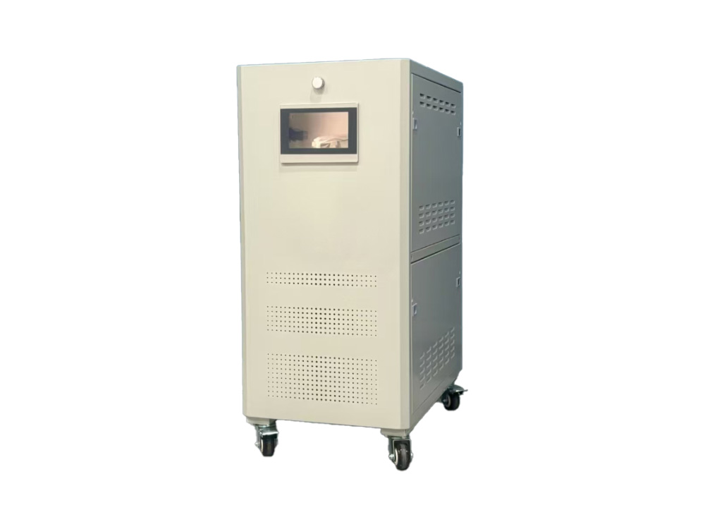
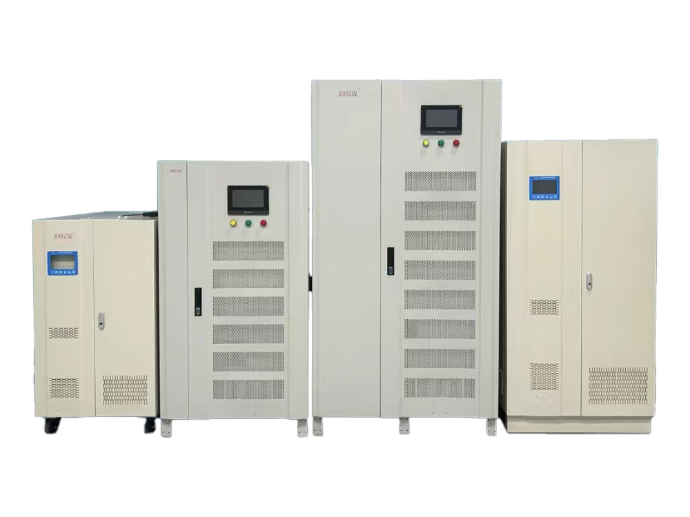
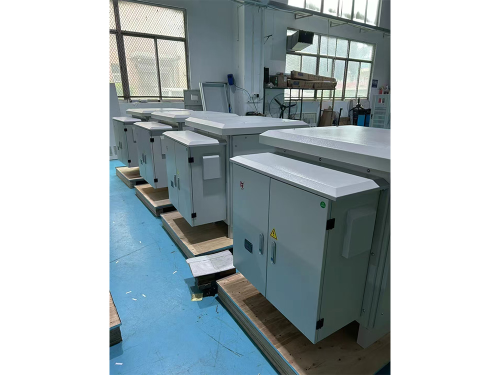
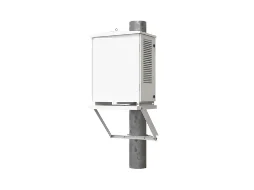
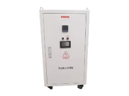
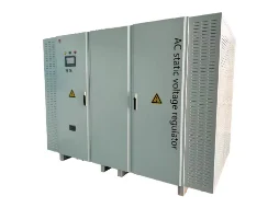
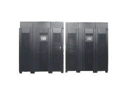
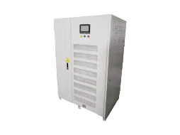
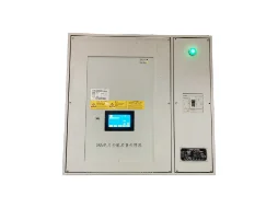
4. Appearance of the product
 Installation and wiring
Please read the contents as below before installation and wiring.
● Before installation and wiring, please make sure to cut off input power to prevent electric shock.
● The product must be installed and tested by trained and qualified personnel.
5-1. Inspection before installation
(1) Check if the model and specification of the product are consistent with the content of your order, especially the capacity, input/output power values, etc.
(2) Check if the articles specified in the factory documents (like Instruction, qualification certificate) and order are complete.
(3) Check if there is any electric component inside the regulator cabinet damaged during the transport.
(4) The fasteners of the regulator must be fastened reliably without disconnection of any wire. If there is any fastener falls off, fasten the wire especially the control component which is not allowed to be loosened or poorly connected.
(5) After arrival of the regulator, please open the box to check and install it within one month in case of any quality problem when it is not used for a long time.
5-2. Installation and wiring
(1) Positioning
① After inspected as qualified, the regulator can be positioned. During this process, please make sure the body and the components inside of the regulator are free from being damaged.
② After positioning the regulator, make sure the base of the regulator receives a uniform stress and its body is positioned in a stable manner.
③ There should be enough space around the regulator for ventilation and maintenance.
(2) Selection of cables:
① During the wiring, please select proper cables and lugs to ensure a reliable connection of input and output terminals.
② In selecting wires, do consider the conditions of cooling, environment, pavement and transmission distance for the load current capacity.
③ The specification of the input and output lines shall be determined by the customer based on the capacity of the regulator. Make sure to make some allowance. It is suggested to select copper wires by 3.5A/mm2 for the regulator.
(3) Cable connection:
① Connect the input power line to the input line terminal inside the regulator cabinet (marked with ‘Input’ character and phase line identifications like ‘R’, ‘S’ and ‘T’).
② Connect the load line to the output line terminal inside the regulator cabinet (marked with ‘Output’ character and phase line identifications like ‘U’, ‘V’ and ‘W’).
③ Connect the input zero line and the load zero line to the corresponding zero line terminals (marked with zero line identification ‘N’) inside the regulator cabinet. If there is no load zero line, you don’t have to connect.
④ Shell protective grounding: Connect the grounding line to the grounding line interface of the regulator (marked with ‘〨’)
(4) Wiring diagram:

Attention:
●The above wiring diagram is only for reference and should be subject to the identifications on the regulator.
●During the wiring, make sure to connect the wiring terminals as per the identifications. Do not connect the input and output wires, phase line and neutral line in a wrong way! The neutral line and grounding line should not be mixed and the grounding line should not be omitted. Any wrong connection of line may lead to failure of the regulator or even cause damage to the regulator.
●Do connect the neutral line, otherwise, the regulator will not work in normal. If the machine requires no neutral line, please tell us when ordering.
●The wiring from power supply to regulator and from the regulator to the load line should be well contacted and able to withstand the rated current from the regulator.
6. Operation
6-2. Operation of the display control panel (The following diagram is only for reference and it shall be subject to the actual display.)
(1) Panel:

(2) Main functions:
1) Display of the voltage of input line and output line in a real-time manner.
2) Display of the phase voltage of each phase in a real-time manner.
3) Display of output load current in a real-time manner;
4) Setting of voltage stabilization precision and voltage stabilization value of each phase.
5) Setting of the voltage stabilization speed as well as the overvoltage, undervoltage value and overcurrent value.
6) Control and indication of the two output states of voltage stabilization and bypass.
7) Indication of overcurrent, overvoltage, undervoltage, phase failure, motor and other failures.
(3) Setting instructions:
It shall be borne in mind that all set voltage values are phase voltage settings rather than line voltage settings.
1) Correction of phase voltage and current:
If the correction of voltage and current is required, please long press AUTO/MANUAL key to switch the voltage regulator to MANUAL mode; If required, the parameters shall be reset in AUTO/AVR mode.
Correction of Phase A voltage:
Long press SET key for the first time 5 seconds to display the settings interface (the SWITCH key may be pressed for exit upon display of the settings interface), then a symbol ‘A’ appears and flickers in the upper right corner of the LCD screen and corresponding voltage correction interface pops up, now the Phase A voltage may be corrected by increase/decrease key and standard voltmeter.
Correction of Phase B voltage:
Short press SET key for the first time, then a symbol ‘B’ appears and flickers in the upper right corner of the LCD screen and corresponding voltage correction interface pops up, now the Phase B voltage may be corrected by increase/decrease key and standard voltmeter.
Correction of Phase C voltage:
Short press SET key for the second time, then a symbol ‘C’ appears and flickers in the upper right corner of the LCD screen and corresponding voltage correction interface pops up, now the Phase C voltage may be corrected by increase/decrease key and standard voltmeter.
Correction of input phase voltage:
Short press SET key for the third time, then a symbol ‘ABC’ appears and flickers in the upper right corner of the LCD screen and corresponding voltage correction interface pops up, now the input voltage may be corrected by increase/decrease key and standard voltmeter.
Correction of Phase A current:
Short press SET key for the fourth time, then a symbol ‘A’ appears and flickers in the upper right corner of the LCD screen and corresponding voltage correction interface pops up, now the input Phase A current may be corrected by increase/decrease key and standard ampere-meters.
Correction of Phase B current:
Short press SET key for the fifth time, then a symbol ‘B’ appears and flickers in the upper right corner of the LCD screen and corresponding voltage correction interface pops up, now the input Phase B current may be corrected by increase/decrease key and standard ampere-meters.
Correction of Phase C current:
Short press SET key for the sixth time, then a symbol ‘C’ appears and flickers in the upper right corner of the LCD screen and corresponding voltage correction interface pops up, now the input Phase C current may be corrected by increase/decrease key and standard ampere-meters.
Note:
The phase voltage must be corrected when the voltage is higher than 200V.
The phase current must be corrected when the current is larger than 20A.
2) Output voltage settings:
These are stable phase output voltage settings and they have been set well before delivery, the users may reset the stabilized voltage depending on their actual needs by the method listed as follows:
Phase A output voltage settings:
Short press SET key for the seventh time on the settings interface, then the symbol ‘A’ and “Voltage Settings” interface flickers in the upper right corner(the voltages of dividing and unified voltage regulator are 220V and 380V respectively), set the required
stabilized voltage by increase/decrease key and complete output voltage settings;
Phase B output voltage settings:
Short press SET key for the eighth time on the settings interface, then the symbol ‘B’ and “Voltage Settings” interface flickers in the upper right corner(the voltages of dividing and unified voltage regulator are 220V and 380V respectively), set the required
stabilized voltage by increase/decrease key and complete output voltage settings;
Phase C output voltage settings:
Short press SET key for the ninth time on the settings interface, then the symbol ‘C’ and “Voltage Settings” interface flickers in the upper right corner(the voltages of dividing and unified voltage regulator are 220V and 380V respectively), one may set to the
required stabilized voltage by increase/decrease key and complete output voltage settings;
3) Over-current protection value settings
Short press SET key for the tenth time on the settings interface, then the “Current Settings” interface flickers, one may set to the required maximum protection current value by increase/decrease key and complete protection current settings(such function is ready in the factory settings and the user settings are not necessary in general);
4) Speed settings:
Short press SET key for the eleventh time on the settings interface, then the “Speed Settings” interface flickers, one may set to the required voltage regulation speed by increase/decrease key and such speed is inversely proportional to the set value (such function is ready in the factory settings and the user settings are not necessary in general);
5) Over-voltage protection value settings:
Short press SET key for the twelfth time on the settings interface, then the “Over-voltage Settings” interface flickers, one may set to the required maximum protection voltage by increase/decrease key and complete over-voltage protection settings (such function is ready in the factory settings and the default value is 250V, the user settings are not necessary in general);
6) Under-voltage protection value settings:
Short press SET key for the thirteenth time on the settings interface, then the “Under-voltage Settings” interface flickers, one may set to the required under-voltage protection voltage by increase/decrease key and complete under-voltage protection settings (such function is ready in the factory settings and the default value is 185V, the user settings are not necessary in general);
7) Voltage regulation precision settings:
Short press SET key for the fourteenth time on the settings interface, then the “precision settings interface” flickers, one may set to the required voltage regulation precision by increase/decrease key and the precision is directly proportional to the set
value (such function is ready in the factory settings and the default value is 3-5V, the user settings are not necessary in general); if there are large voltage fluctuations in the user’s power grid, the precision value may be set a little higher for effective
maintenance of the stable performance of the voltage regulator.
8) Switching between display voltages:
Short press “SWITCH” key and the Phase A, Phase B, phase C, phase AB, phase AC and phase BC voltage will be displayed in turns on LCD display, the phase voltage and line voltage will be displayed alternately.
9) Switching between “AVR” and “BY PASS” work modes
The default mode is “AVR” work mode when the device is started, now one can press “AVR/PASS” key for 3S and switch to “BY PASS” mode, the luminescent characters “BY PASS” are shown on LCD display, one may press “AVR/PASS” key once again for 3S and switch to “AVR” mode, the luminescent characters “AVR” and “AUTO” will be shown on LCD display!
10) Switching between “MANUAL” and “AUTO” work modes:
The default mode is “AVR” work mode when the device is started, now one can press “AUTO/MANUAL” key for 3S, release and switch to “MANUAL” mode, the “MANUAL” indicator lamp will be on, now one may press “Increase” key or “Decrease” key to regulate the voltage to its required voltage value, such function is designed mainly for emergency use when the “Auto Function” is out of control.
7. Notes
The following matters need user’s special attentions. To protect your life safety as well as the product and the equipment connected to the product, please read it carefully before use and follow it strictly during use.
7-1. Notes on usage
(1) The regulator must be installed, operated and maintained by trained personnel with electrician qualification. Irrelevant personnel are not allowed to operate the regulator.
(2) Before installing and maintaining the regulator, make sure to cut off the input power to prevent electric shock or damages to the product.
(3) The wiring must be firm to prevent falling off and sparking, or the oxidation of the contact due to the heated resistance as it is too large. Loose contact will also lead to automatic switch to the bypass.
(4) The input and output lines of the regulator must be laid rationally to prevent it from being treaded and worn, resulting in leakage accident.
(5) The regulator must be properly grounded and user shall bear the responsibility for the electric shock accident or injuries caused by the failure of connecting the grounding line.
(6) The grounding line of the regulator cannot be connected to the service facilities as heating pipeline, water supply line, gas pipeline, etc. to prevent infringing the third party’s rights and interests or causing any damages.
(7) When the regulator is running, do not dismantle the regulator and touch the parts inside or pull the input and output lines of the regulator to prevent from electric shock accident or other electric safety accident.
(8) Please do not operate the regulator with wet hands.
(9) Please do not dismantle or reform the regulator without authorization to avoid failures, electric leakage or fire.
(10) Do not stand or put weight on the regulator body. Do not let the foreign matters especially conductors enter the body through heat emission holes or other parts to avoid failures, electric leakage or other safety accidents.
(11) It is forbidden to clean the regulator with corrosive detergent or the detergent that will corrode plastics and coatings.
(12) Please do not put any articles around the regulator so as not to block the ventilation.
(13) When you finish using the regulator, switch it off and pull out all the external wires on the terminal plate.
7-2. Notes on power supply
(1) Please select the product according to the actual power of all the electric equipment with a proper allowance.
(2) The input voltage is allowed to fluctuate between ±15% and 30%. This range is subject to the range of fluctuation of the regulator purchased by you.
(3) The relative harmonic content of the voltage waveform is not over 10%. If the power factor is too low or voltage is too low, you need to reduce the capacity of the regulator.
(4) If the lightning is very frequent at the place where the regulator is used, please mount lightning protection device and add the device to your order.
※In case that there is any special conditions that are not mentioned above, please confirm with the agent when placing an order, or consult with us during the use.
8. Daily maintenance
Attention:Before maintenance, please make sure to cut off the input power to avoid electric shock accident or other safety accidents.
8-1. Check the working state of the regulator regularly during the use:
(1) Check if the regulator displays the right voltages.
(2) Check if the load exceeds the rated value.
(3) Check if the input voltage is beyond the fluctuation range that is permitted.
In case of any abnormal phenomenon occurs during the patrol inspection, treat it immediately. If the problem cannot be treated on spot, contact the supplier or the factory timely for the solutions so as not to damage the equipment.
8-2. It is suggested to maintain the regulator regularly. The maintenance includes:
(1) Clean SCR component of the regulator carefully and clean up the dust and dirt to avoid line failure caused by the dampened dust.
(2) Check if the fasteners and wiring contacts inside the body loosen. In case of any unreliable connections or poor contact, deal with it immediately.
(3) Repair or change the components which are broken or damaged timely.
9. Troubleshooting
Attention:Before repairing, please make sure to cut off the input power to avoid electric shock accident or other safety accidents.
9-1. Any problems of the regulator discovered by the user during use shall be treated in reference of the following contents.
|
Phenomenon
|
Cause
|
Solution
|
|
Unstable
|
The bypass of the
|
Check if there is a bypass. If so,
|
|
output voltage
|
regulator cannot stabilize the voltage by itself.
|
check the fault display.
|
|
The output voltage is not regulated, and one phase voltage is high and the other phase voltage is low.
|
Is the neutral wire connected or virtually connected?
|
① Check if the neutral line at the wiring port is connected.
② Check if the neutral line of the grid is connected
|
|
Abnormal voltage or too low voltage occurs after manual bypass
|
①Input out-phase
②Too low input voltage
|
① Check if the input has phase loss. If so, ask a professional to seek the cause for the phase loss.
②Check if the input voltage is compliant with the minimum limit range of the regulator.If so, change a machine which has a higher range of regulation.
|
|
Fan fails
|
① Temperature inside the machine is lower than 55°℃;
② The plug of the fan loosens;
③ The fan is burnt.
|
① It is a normal phenomenon.
② insert the plug into the socket firmly.
③ Change the fan.
|
|
The regulator has a smell
|
① The coil is hot;
② Severe carbon brush wear;
③ The color of the coil of the transformer changes due to the overcurrent.
|
① Check if the load is within the rated range of the machine;
②Replace the carbon brush assembly;
③The load is overloaded for a long time, which reduces the load.
|
|
The output voltage drops a lot after the bypass
|
The bypass AC contactor fails.
|
Replace the bypass AC contactor.
|
|
The display bar fails to display any value but the regulator is still normal after it is switched on.
|
①The connecting line between the display board and the main board is loosened.
②The display is damaged
|
① Re-plug the connecting line
②Replace with new display
|
|
Abnormal value occurs after a new regulator is installed.
|
Incorrect wiring.
|
Check if the phase line and zero line are correctly connected and if the zero line is connected.
|
|
Input switch tripped
|
①start when there is load
②incorrect wiring
|
Turn off the load on the back of the regulator
②Check if the phase and neutral lines are properly wired
|
 English
 Chinese