Brief introduction
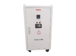
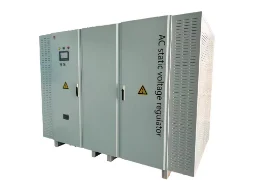
Function:The voltage regulator series products are developed for sites with long power supply radius and large load changes, such as rural power grids, resulting in low voltage at the end of the power supply. This product plays a role in regulating and stabilizing the back-end voltage, effectively solving the problem of low voltage at the end of the distribution network.
2、 Working principle
This series of products mainly consists of AC bypass units, power transformers, rectifier units, inverter units, input-output distribution and protection, communication units, etc.
When the input voltage of the mains is within the allowable fluctuation range, the system operates in AC bypass mode; When the increase in load leads to the phenomenon of "low voltage" or the decrease in load leads to the phenomenon of "high voltage", the system switches from bypass mode to rectifier inverter mode. The rectifier unit is controlled by a digital signal processor to output a stable internal DC voltage from the IGBT module. At the same time, the rectifier unit has a voltage stabilization function, which can suppress fluctuations in the input mains voltage. The inverter unit calculates the required compensation voltage based on the current mains voltage, and the corresponding voltage output by the inverter unit is superimposed on the mains voltage through a transformer to supply the load together, thus solving the problem of "low voltage" or "high voltage".

Figure 1 Schematic diagram of voltage regulator
3、 Technical specifications
|
DNAM single-phase terminal voltage compensation device
|
|
Electrical specifications
|
input voltage
|
120V -270V
|
|
phase number
|
single-phase
|
|
rated output voltage
|
220Vrms/230Vrms panels can be set
|
|
frequency
|
50Hz±10%
|
|
rated output capacity
|
10kVA
|
20kVA
|
30kVA
|
|
Inverter overload capacity
|
<1.05 times the rated power can be overloaded for a long time, 1.05 to 1.1 times the power can be overloaded for 1 hour before switching to the bypass, 1.1 to 1.25 times the power can be overloaded for 10 minutes before switching to the bypass, 1.25 to 1.5 times the power can be overloaded for 1 minute before switching to the bypass, and over 1.5 times the power can be overloaded for 0.2 seconds before switching to the bypass
|
|
Maximum efficiency
|
>96.5%
|
|
communication interface
|
dry contact
|
1 EPO
|
|
communication
|
RS485, WIFI (optional)
|
|
Environmental Specifications
|
Usage location
|
outdoors
|
|
Working altitude
|
Below 1000 meters, use with reduced rating when above 1000 meters
|
|
Storage temperature
|
-20℃ ~ 70℃
|
|
Operating Temperature
|
-10℃ ~ 40℃
|
|
humidity
|
Less than 95% RH, no condensation of water droplets
|
|
vibration
|
Less than 5.9 meters per second ² (0.6g)
|
|
structure
|
Protection level
|
IP43
|
|
size
|
600*600*920
|
|
Net weight of integrated product
|
75kg/90kg/100kg
|
|
cooling method
|
Smart Air Cooling
|
|
Specifications
|
DNAM three-phase terminal voltage compensation device
|
|
Rated input voltage
|
380V
|
|
input current
|
152A
|
|
rated output voltage
|
390V
|
|
output current
|
148A
|
|
Communication output type
|
(3W N PE) three-phase four wire
|
|
Rated capacity
|
100kVA
|
|
Input Voltage
|
AC 380V( 32% ,-40%)
|
|
Rated grid frequency
|
50Hz±5%
|
|
voltage regulation accuracy
|
1%
|
|
response time
|
<5ms
|
|
Total voltage distortion rate
|
<4%
|
|
Ambient Temperature
|
-25 ℃~55 ℃ (derating at>45 ℃)
|
|
Working environment humidity
|
<95%RH , No condensation
|
|
cooling method
|
Smart Air Cooling
|
|
Protection level
|
IP44
|
|
Working altitude
|
<4000 meters (use with reduced rating if greater than 2000 meters)
|
|
noise
|
<65dB
|
|
protection function
|
Overload protection, over temperature protection, over voltage protection, under voltage protection, over-current protection, over frequency protection, under frequency protection, etc
|
|
interface display
|
Equipment, power grid, load, temperature data display, parameter setting, operating status display, power on/off control, etc
|
|
contact method
|
Modbus-RS485 、WIFI
|
|
size
|
451mm (width) x 1020mm (height) x 800mm (depth)
|
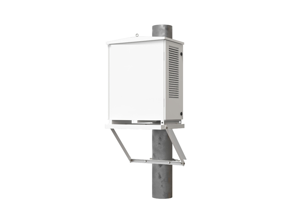
4、 Installation method
The installation method includes the installation of outdoor pole triangular brackets, as shown in Figure 3-1.

Figure 3-1 Schematic diagram of installation method for voltage regulator
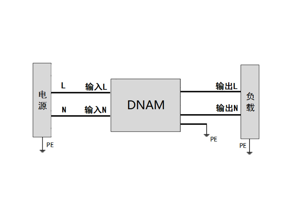
3.2 Electrical Installation
3.2.1 Single machine power distribution
When distributing power individually, the connection methods of live wire, N-wire, and PE wire are shown in Figure 3-2.

Figure 3-2 Schematic diagram of single machine power distribution wiring
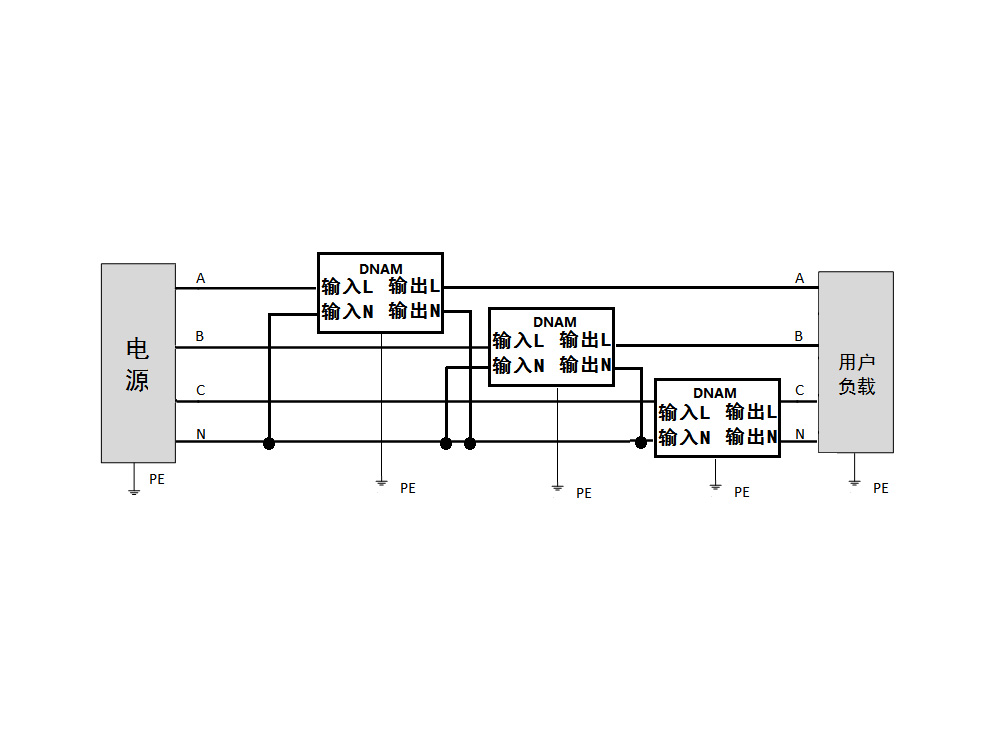
3.2.2 Three phase power distribution group
When assembling three phases, they work independently. The wiring diagram is shown below.

Figure 3-3 Schematic diagram of three-phase group
 English
 Chinese