1-1. Overview
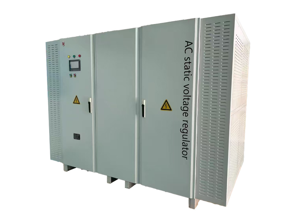
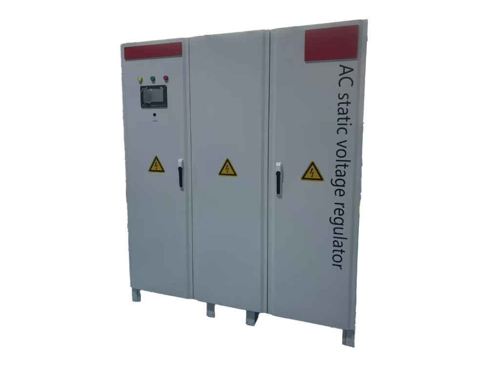
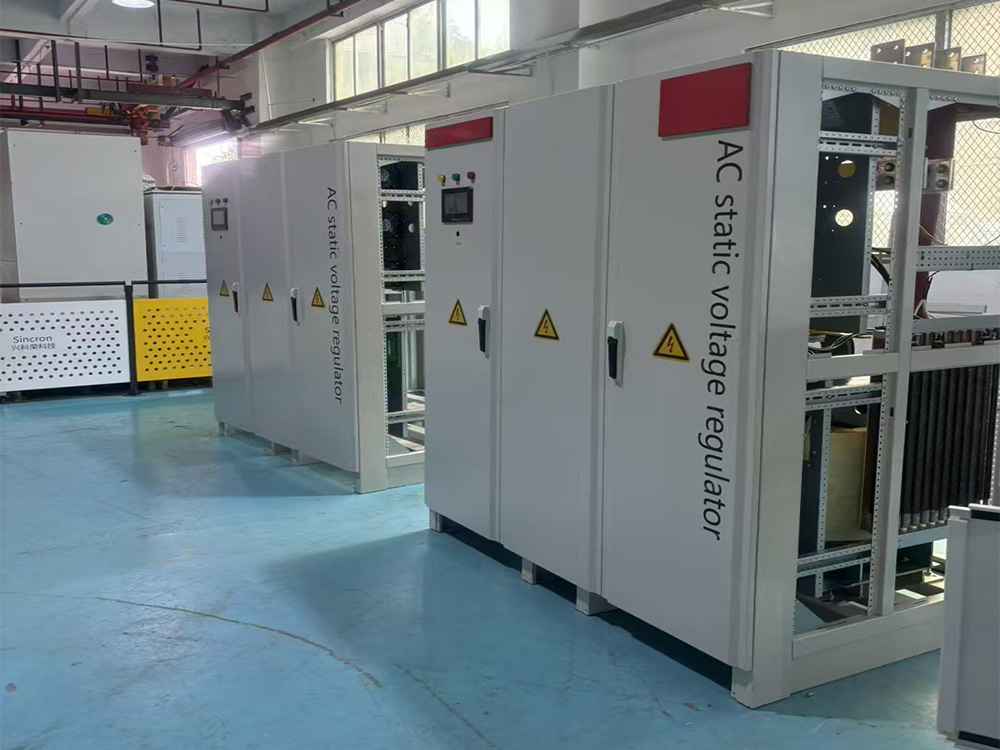
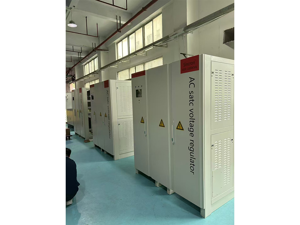
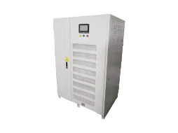
ARS series three-phase digital non-contact voltage regulator (hereinafter referred to as voltage regulator) is a new generation of fast voltage regulator equipment successfully developed on the basis of many years of production of compensating power voltage regulator equipment.
It uses the latest DSP computing metering chip control technology, fast AC sampling technology, current zero-crossing switching technology and fast compensation voltage regulation technology to combine smart meters, fast voltage regulation and fault diagnosis to make products safe, efficient and precise.
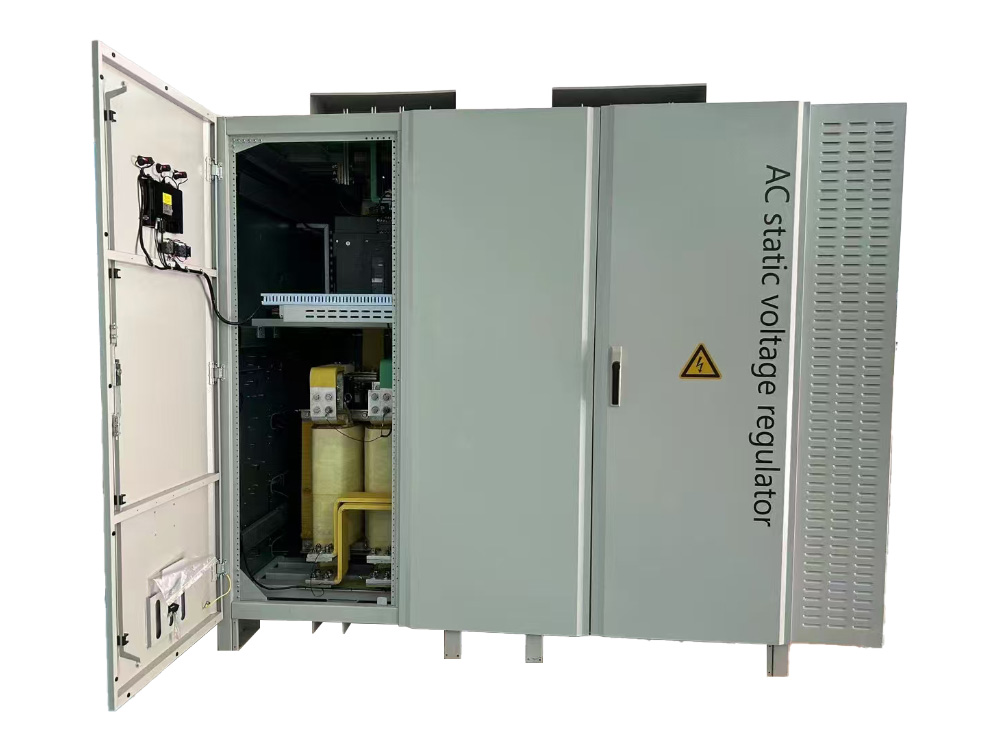
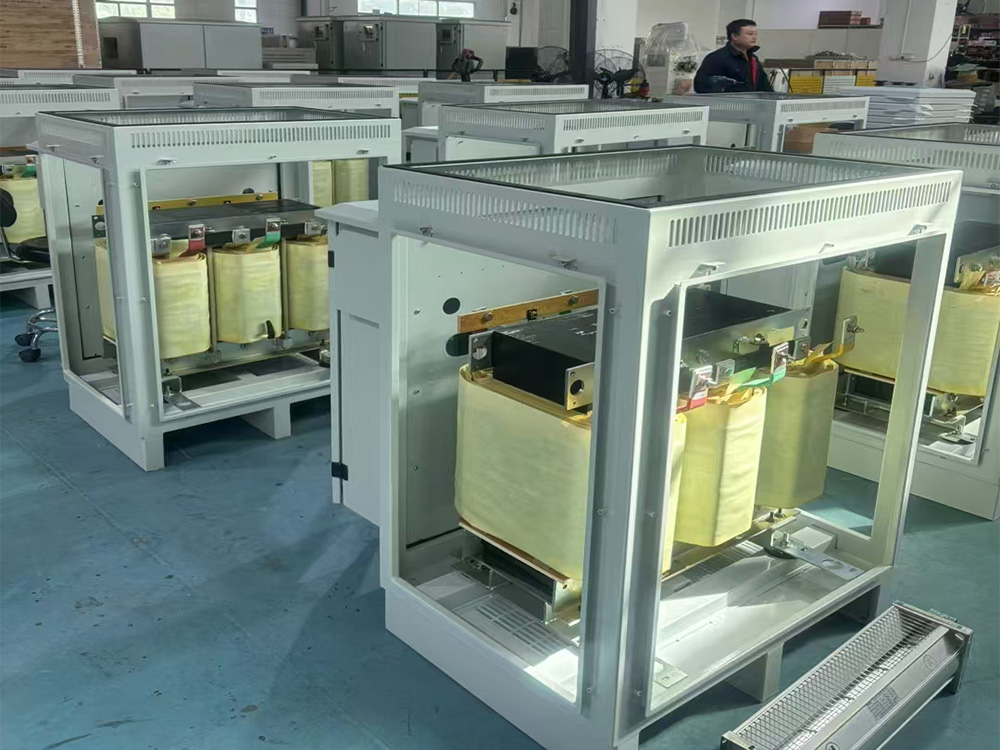
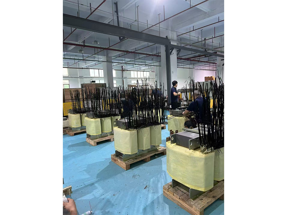
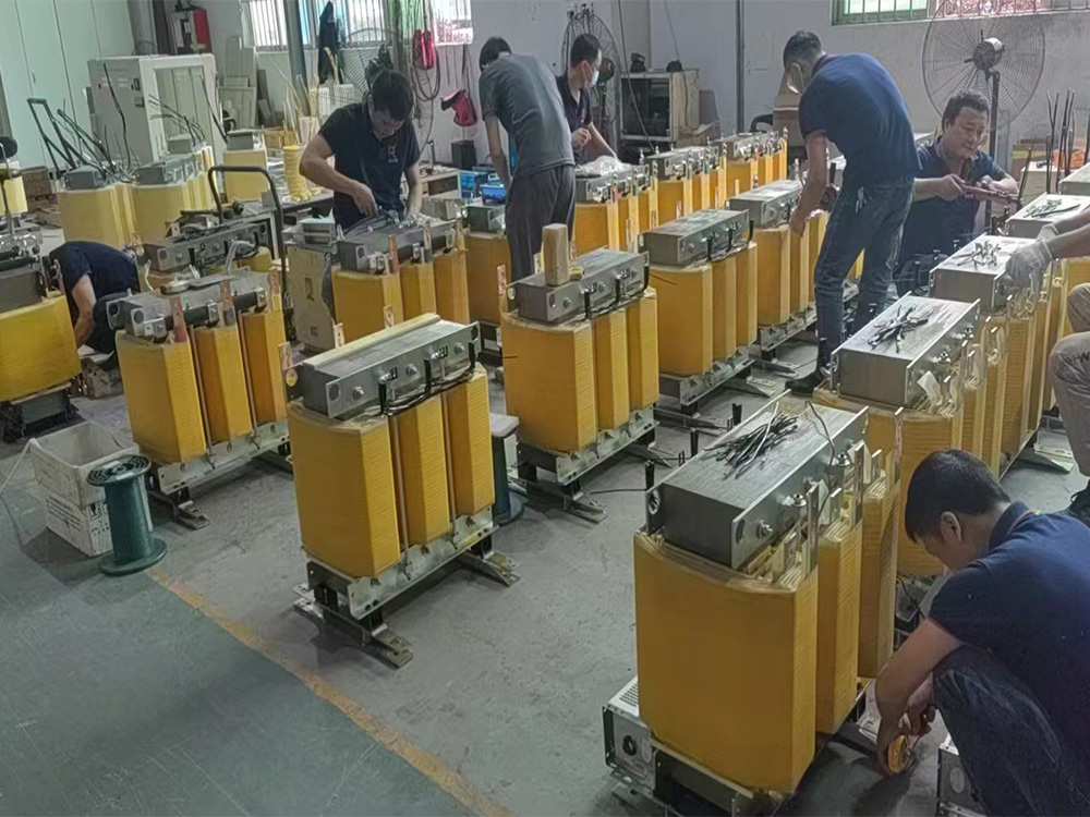
It is mainly composed of isolation transformer, SCR voltage regulator module, MCU control core + high precision current and voltage sampling component, fast voltage regulation technology and safety protection device, which realizes full contactless control, safe, efficient, energy saving and environmental protection. It is the perfect combination of SCR and transformer switching without surge current technology.
The products are widely used in large-scale electromechanical equipment in the fields of industry, transportation, post and telecommunications, national defense, railway, scientific research, etc., which require high-precision and stable voltage.
1-2. Features
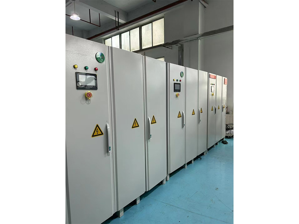
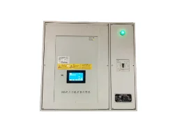
(1) Intelligent instrument display: The smart meter displays the effective values such as line voltage, phase voltage, current and power in real time, clear, accurate and high resolution. The membrane button operation is safe and reliable.
(2) Three-phase regulation: The output voltage unbalance is less than 1%,ensuring the accuracy of the output voltage of each phase.
(3) Wide application range: Wide voltage regulation range, can meet the needs of places and equipments with poor power supply grid quality and large voltage fluctuation range.
(4) High-speed reaction: The regulation reaction speed is within 40 milliseconds, and no voltage change is affected for any computer automation, equipment and instruments.
(5) Complete protection functions: Fault display and protection functions such as overload, overvoltage, undervoltage, and short circuit are provided to ensure safe operation of the regulator and load.
(6) Preset function is strong: The protection limit can be set arbitrarily.
(7) Strong overload capability: The whole machine adopts high-quality components, has good performance, can be used continuously under 100% rated load conditions, and can withstand transient (10 millisecond) overload (10 times) without damaging the machine.
(8) Adaptability: It has strong adaptability to power grid and load, and can reliably and continuously work stably under various harsh power grids and complicated load conditions.
(9) No distortion: Adopt current zero-crossing switching technology, no interruption current during the switching process, no surge current, and the waveform is not distorted.
(10) Low loss: minimum power loss, no-load loss less than 0.5%, saving customers a lot of electricity.
(11) Bypass function, easy to maintain: It can be switched between “regulation” and “bypass direct power supply”, which is convenient for fault repair.
1-3. Product schematic
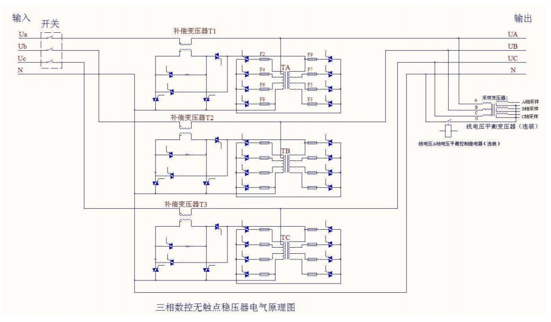
The three-phase, non-contact voltage regulator digitally samples and processes the output voltage to obtain an accurate output voltage. By comparing the output voltage and the set voltage, the regulator component is adjusted to obtain the required voltage.
2. Technical Parameters
2-1. Product Specifications:
|
Rated Capacity:
|
6KVA~2500KVA
|
|
Phase:
|
Three phase
|
|
Input regulation range:
|
380V±15%
|
380V±20%
|
380V±30%
|
|
Output voltage:
|
380V
|
|
Voltage regulation accuracy:
|
±1%
|
±1.5%
|
±2%
|
|
Effectiveness:
|
≥99%
|
|
Frequency:
|
The input voltage frequency is 45 - 65Hz, and the output frequency should also be the corresponding frequency.
|
|
Reaction speed:
|
<40 milliseconds
|
|
Voltage regulation speed:
|
30 milliseconds
|
|
Insulation grade:
|
Class E
|
|
Insulation resistance:
|
Insulation resistance of the whole machine to ground >5MΩ
|
|
Dielectric strength:
|
Sinusoidal AC voltage 2500V/1min without flash path and breakdown
|
|
Output waveform:
|
Output waveform is distortion free, no harmonic increment
|
|
Instantaneous overload capability:
|
2 times rated current
|
|
Display method:
|
LCD touch screen display
|
|
Way of working:
|
Long-term continuous operation
|
|
Protective function:
|
Overload, overvoltage, undervoltage, phase loss, short circuit protection
|
|
Heat dissipation method:
|
Temperature controlled forced air cooling
|
Remarks:
① The rated capacity of the regulator is calculated as follows:

In the formula:
P — regulator rated (output) capacity (KVA)
m - phase number single phase: m=1 three phase: m=3,
I2 — rated output current (A)
U2 — rated output voltage (V) (three phase is line voltage)
② The above is the technical parameters of our regular products, not as the basis for customer acceptance of products, product acceptance should be based on the technical parameters in the contract.
③ Customers who have special requirements can consult with the relevant departments of the company.
2-2. Local specifications:
|
Number:
|
|
Output voltage:
|
V
|
|
Product number:
|
|
Output current:
|
A
|
|
Product name:
|
|
Voltage regulation accuracy:
|
%
|
|
Rated Capacity:
|
KVA
|
Cooling method:
|
Self-cold Air cooled
|
|
Phase:
|
|
Weight:
|
kg
|
|
Voltage regulation range:
|
V
|
Dimensions:
|
× × mm
|
3. Environmental requirements
3-1. When the product is used, its environmental requirements are:
(1) The regulator should be used indoors.
(2) No conductive or explosive dust, no corrosive metal or gas, steam or oil mist that destroys insulation.
(3) Good ventilation.
(4) The basis of leveling and solidity.
(5) If the altitude does not exceed 1000m, it must be derated when it is greater than 1000m. (Note: When the altitude exceeds 1000m, the load capacity of the regulator will decrease as the altitude increases.)
(6) Ambient air temperature: the lowest temperature is -5 °C, and the highest temperature is +40 °C. The daily average temperature of the cooling air does not exceed +30 ° C, the annual average temperature does not exceed +25 ° C, and the temperature change rate of the working environment should not exceed 5 K / h. (Note: When the operating ambient temperature is higher than the specified limit, the load capacity of the regulator will be reduced.)
(7) Relative humidity: ≤96% RH (40 °C ± 2 °C without condensation).
(8) The waveform of the power supply voltage is approximately sinusoidal (THD ≤ 4%).
(9) Transient spike voltage Vp-p≤2000V in the power grid, no lightning strike.
(10) Not exposed to radioactive radiation.
(11) Avoid abnormal mechanical stresses such as shock and vibration.
(12) Not many regulators operate in parallel.
(13) There should be sufficient space for heat dissipation and maintenance around the top and top of the regulator.
3-2. When the product is stored, its environmental requirements are: The product should not be exposed to the sun or rain. It should be stored in a place where it is clean, free of strong mechanical vibration, shock and strong magnetic field, and does not allow all kinds of harmful gases, flammable and explosive materials and corrosive chemicals.
3-3. When the product is shipped, its environmental requirements are:
When the product is transported, it must have the necessary packaging materials. During the transportation, direct rain and snow should be avoided. There should be no severe vibration, impact and back-up.
■ Pay attention:
If there are special conditions of use that cannot meet the above requirements, please consult with the seller at the time of ordering, or consult us at any time during the use.
4. Installation wiring
Please read the following before installing the wiring:
● Before installing the wiring, be sure to cut off the input power to prevent accidents due to electric shock.
● Products must be installed and tested by trained, electrically qualified personnel.
4-1. Pre-installation inspection
(1) Check that the model and specifications of the product are consistent with your ordering information, especially the capacity, input/output voltage values, etc.
(2) Check the factory documents (instructions, certificates, etc.) and other items to be delivered as agreed in the order materials.
(3) Check the electrical components inside the voltage regulator cabinet for damage during transportation.
(4) The fasteners of the voltage regulator must be firm and reliable, and the wiring must not be detached. If it is detached, it should be tightened. In particular, the control insert should not be loose or poorly contacted.
(5) After the regulator arrives, please check and install it within one month to avoid the long-term suspension of the product and affect the quality.
4-2. Installation wiring
(1) In place:
1 After the regulator is qualified, it can be in place. During the in-position process, it is necessary to ensure that the regulator box and the components inside the cabinet are not damaged.
2 After the position is in place, it is necessary to ensure that the pressure regulator chassis is evenly stressed and the cabinet is placed stably.
3 There should be enough room around the location to ensure that the regulator is ventilated, repaired and maintained.
(2) Cable selection:
① When wiring, please select the appropriate cable and wire ear to ensure reliable connection of input and output.
2 Cable selection must take into account factors such as load rate cutoff heat dissipation conditions, environmental conditions, laying methods, and transmission length.
3 The input and output line gauges should be determined by the user according to the capacity of the regulator. Be careful to have a certain margin. It is recommended to connect the copper wire of the voltage regulator to 2.5A/mm2.
(3) Cable connection:
① Connect the input power cable to the input terminal block in the voltage regulator cabinet (labeled “Input” and phase line identification: marked with “A”, “B”, “C”);
② Connect the load line to the output terminal block in the regulator cabinet (labeled "Output" and phase line identification: labeled "a", "b", "c"). ③ Connect the input neutral and load neutral to the corresponding neutral terminal in
the regulator cabinet (marked with the neutral line "N"). If the load has no neutral, it can be exempted.
(4) Chassis protection grounding:
The grounding wire should be connected to the grounding wire of the regulator (marked with the grounding mark “〨”).
● The above wiring diagram is for reference only, please refer to the identification on the voltage regulator.
● When wiring, be sure to connect according to the identification of the terminal block. Do not reverse the input and output. Do not reverse the phase line to the neutral line! The neutral and ground wires must not be confused, and the ground wires cannot be omitted. If the wrong line is connected, the regulator will not work properly or even be damaged!
● The zero line must be connected. If the zero line is not connected, the voltage regulator will not work. If the machine requires no zero line, please ask when ordering.
● From the power supply to the voltage regulator, the voltage and the wire end connector of the voltage regulator connected to the load should be in good contact, firm and reliable, and can pass the rated current of the regulator.
5. Operational use
5-1. Power on
(1) Before powering on, be sure to confirm that the input phase line, output phase line, neutral line, and ground cable are properly connected.
(2) Set the load (device) to which the regulator is connected to the OFF state.
(3) Put the power switch on the voltage regulator on the ON state. At this time, the “Stabilization” light on the display panel lights up, and the digital tube displays the corresponding value.
(4) Check if the display panel displays the required regulated output value. If there is any deviation, reset the regulated output value through the display panel.
(5) Confirm that the output voltage and current are in accordance with the load.
(6) After everything is normal, gradually add the load and conduct a trial run.
(7) Check if the voltage value and current value on the display panel are within the specified range. If each function is displayed within the normal value, it can be used normally.
When the voltage regulator is started with load, it can't exceed 20% of the capacity of the machine. If the voltage exceeds 20% of the capacity, the regulator will burn out the switch; if the load is turned on, the load will not occur. If you need to start up more than 20% of the machine capacity, you need to communicate with the manufacturer and modify the equipment.
5-2. Usage notice
1. The load capacity of the voltage regulator must be balanced to extend the life of the regulator. Do not overload the load for a long time.
2. The regulator is fully protected to ensure safe operation of the regulator and load equipment. details as follows:
(1) Overload protection: If the load current exceeds the set overcurrent value for 20 seconds, the “overload” light is on, the alarm is issued, and the system enters the bypass; if in the bypass state, the overcurrent lasts for 2 minutes and the system automatically trips;
(2) Overvoltage protection: When the actual voltage is higher than the set overvoltage value, the “overvoltage” light is on, and the alarm is continued for 3 seconds to enter the bypass; if in the bypass state, the overvoltage lasts for 5 seconds, the system Automatic tripping.
(3) Undervoltage protection: When the actual voltage is lower than the set undervoltage value, the “undervoltage” light is on, and the alarm is continued for 3 seconds to enter the bypass; if in the bypass state, the undervoltage continues for 5 seconds, the system Automatic tripping.
(4) Phase loss protection: Phase loss protection is the same as undervoltage protection.
(5) Short circuit protection: When the regulator has a short circuit fault, the system automatically trips.
3. If the input voltage is within the regulation range and the output voltage is unstable, check it immediately. For details, please refer to the “Exception Handling Table”.
4. When the temperature of the heat sink on the thyristor reaches 45 °C, the fan on the thyristor will rotate.
5. When the internal temperature reaches 55 °C, the fan on the chassis will rotate.
5-3. Operating instructions for touch screen display control (The following illustrations are for illustration only, and the actual display shall prevail.)
Through the display panel, we can clearly understand the operation of the regulator, and can also set the parameters. Let's look at the function of the display panel and the specific operation method.
Through the display interface, we can clearly understand the operation status of the voltage regulator and also set the parameters. Now let's look at the functions of the display screen and the specific operation methods.
(1) Panel diagram:

1) Real time display of input line voltage and output line voltage;
2) Real time display and output of each phase voltage;
3) Real time display and output of each phase current;
4) Control and indication of voltage stabilizing and mains power output states;
(2) Parameter setting: enter the first level password to enter the parameter setting page. The default password is 123456.

1) A, B, C phase stable voltage setting: This setting is the setting of the output stable voltage value of each phase, which has been set at the factory. The user can reset the stable voltage value according to actual needs.
2) Setting of overvoltage, undervoltage, overcurrent protection value and voltage stabilization accuracy: you need to enter a secondary password, please contact your dealer or manufacturer The setting of overvoltage, undervoltage and overcurrent protection values can ensure the safe operation of the voltage regulator and the load.The protection value has been set at the factory, and the user does not need to change it. If you need to change it, please contact the manufacturer or dealer.
(3) Alarm record: all fault alarm information can be viewed

(4) Curve chart: you can view the curve chart of voltage and current, from which you can clearly see the curves of input voltage UAB, output voltage Uan, Ubn, Ucn, and current Ia, Ib, Ic, and support the export of record forms.


(5) System menu: You can view the specifications and parameters of the machine, as well as the manufacturer's settings, system settings, and password modification. For security reasons, you can only view the specifications and parameters. Other functions require multiple passwords to modify. You can ignore them.
 6. Precautions
The following are special considerations for users. In order to ensure your life safety and protect the safety of the products and connected equipment, please read them carefully before use and strictly observe them when using them.
6-1. Precautions for use
(1) The regulator must be installed, operated, and maintained by trained, electrically qualified personnel to prevent unrelated personnel from operating the unit.
(2) Before installing and servicing the regulator, be sure to cut off the input power to avoidelectric shock or product damage.
(3) The wiring must be tightly pressed to prevent the ignition from falling off and the contact resistance is too high to cause the contact oxidation. The loose contact will automatically bypass when the contact is used.
(4) The input and output connections of the regulator must be arranged reasonably to prevent the stepping and grinding, resulting in leakage accidents.
(5) The voltage regulator must be properly grounded. The user is responsible for electric shock or human injury caused by the operation of the grounding line.
(6) The ground wire of the voltage regulator must not be connected to public facilities such as heating pipes, water supply pipes and gas pipes to avoid infringement of third party rights or harm.
(7) When the voltage regulator is running, do not open the input/output wiring of the internal parts of the chassis or the pull-up regulator to prevent electric shock or other electrical safety accidents.
(8) Do not operate the regulator when the hand is wet;
(9) Please do not disassemble and modify the voltage regulator to avoid malfunction, electric leakage or fire.
(10) Do not stand or place heavy objects on the regulator box. Do not allow debris, especially conductive objects, to enter the chassis from the heat dissipation holes or other parts to avoid malfunction, electric leakage or other safety accidents.
(11) It is strictly forbidden to clean the regulator with a corrosive cleaning agent or a solvent that has a dissolution effect on the plastic and the paint film;
(12) Avoid stacking objects around the regulator and hinder the circulation of air;
(13) When the regulator is not used, turn off the power switch and remove the external wiring on the terminal block.
6-2. Power supply precautions
(1) Select this series of products according to the actual power of the electrical equipment used and leave a suitable margin;
(2) The input voltage is allowed to fluctuate within ±15% to 30%; this range depends on the fluctuation range of the regulator you purchased.
(3) The relative harmonic content of the voltage waveform should not exceed 10%. If the power factor is too low or the voltage is too low, you need to reduce the capacity of the device.
(4) If there is frequent lightning in the area where the regulator is used, lightning protection should be installed. Please specify when ordering.
※ If there are special conditions of use that cannot meet the above requirements, please consult with the seller at the time of ordering, or consult us at any timeduring the use.
7. Routine maintenance workAlways cut off the input power before performing maintenance to avoid electric shock or other safety incidents.
7-1. Regularly patrol the working state of the regulator during use:
(1) Check if the voltage displayed by the regulator is normal;
(2) Check if the load exceeds the rated value;
(3) Check if the input voltage exceeds the allowable fluctuation range.
(4) Check if there is a bypass display. If there is a bypass display, press the “Information Query” button to query the fault.If an abnormal phenomenon occurs during the inspection process, it should be dealt with in a timely manner. If it cannot be processed in time, the supplier or manufacturer should be notified in time to contact the solution to avoid damage to the equipment.
7-2. It is recommended to maintain the regulator regularly, including:
(1) Carefully clean the regulator thyristor regulator to remove dust and dirt, so as to avoid dust and moisture leading to control line failure.
(2) Check if the fasteners and connecting ends in the chassis are loose. If there is any connection or poor contact, it should be handled in time.
(3) Components found to be faulty or damaged should be repaired or replaced in time.
8. Abnormal situation handlingAlways turn off the input power before performing maintenance to avoid electric shock or other safety incidents.
8-1. The user finds that there is a problem with the regulator during use. You can refer to the following for processing:
|
Phenomenon
|
Reason
|
Approach
|
|
Unstable output voltage
|
The regulator is bypassed and cannot be automatically regulated.
|
Check if the system is bypassed. If yes, press the "Information Query" button to view the fault code display.
|
|
System bypass
|
Machine malfunction
|
1 Re-close, press the "Information Query" button to see which phase has a fault code display.
2 Check if the fuse is burnt out. If it is, replace the fuse, replace it and burn it again. Replace the thyristor regulator or report it to the manufacturer.
3 If the fault is overcurrent or overvoltage or undervoltage, check whether the set value is correct. If it is correct, you need to report it to the manufacturer.
|
|
Abnormal voltage or voltage is too low after manual bypass
|
1 Input phase loss
2 input voltage is too low
|
1 Check if the input is missing. If so, find a professional to find the cause of the missing phase.
2 Check that the input voltage meets the minimum input range of the regulator, and if so, switch the machine with a wider voltage regulation range.
|
|
Fan does not work
|
1 The temperature inside the machine is less than 55 °C;
2 The fan plug is loose;
3 The fan burned out.
|
1 is a normal phenomenon;
2 Plug in the plug;
3 Replace the fan.
|
|
The regulator has an odor
|
1 The thyristor breakdown that controls the protection resistor causes the resistance to heat up;
2 The protection relay with load start-up fails;
3 Transformer coil overcurrent color.
|
1 Replace the protective resistor thyristor;
2 Replace the protective relay;
3 Report to the manufacturer.
|
|
The output voltage drop is very large after bypassing
|
The bypass AC contactor has failed.
|
Replace the AC contactor.
|
|
The display panel does not display the value after booting, but the voltage is normal.
|
There is a problem with the display board.
|
Replace the display panel.
|
|
The value is abnormal after the new installation
|
Wiring error.
|
Check that the phase and neutral wires are wired correctly and that the neutral wires are connected.
|
|
Switch trip
|
After the system is bypassed, overvoltage or undervoltage or overcurrent occurs again.
|
Turn the automatic bypass to manual bypass, press the "information query" but ton to view the fault, and if there is a fault, follow the system bypass method.
|
※ If you have not been able to solve the problem after checking and taking the above measures, please contact the supplier or manufacturer for any problems.
9. Download GoogleWhen ordering, please specify the specific specifications of the products ordered:
(1) Regulator type (selection of voltage regulator components)
(2) Number of phases
(3) Rated capacity (KVA)
(4) Input voltage (V)
(5) Output voltage (V)
(6) Frequency (Hz)
(7) Wiring method: three-phase four-wire system, three-phase three-wire system (no zero line)
(8) Additional mounting options: line voltage balance and lightning protection.
(9) Quantity (set)
 English
 Chinese