Overview of DNSVG Dynamic Power Factor Compensation Device Technology
1. DNSVG is used to compensate for reactive power
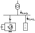
Figure 2.2 System with DNSVG reactive power compensation device
Assuming that the load consumes inductive reactive power (which is generally the case for industrial users) Q
LAt this point, control the SVG to generate capacitive reactive power and take Q
SVG=Q
LIn this way, during the process of load fluctuations, Q can be guaranteed
S=Q
SVG-Q
L0
If for complex compensation objects such as the power grid, when it is necessary to provide inductive reactive power to the grid, the SVG can be controlled to generate inductive reactive power and Q can be taken
SVG=Q
CIn this way, during load fluctuations, Q can still be guaranteed
S=Q
SVG-Q
C0
In addition, SVG generates almost no harmonics while compensating for reactive power in the system. More importantly, SVG can also provide multifunctional comprehensive compensation for power quality issues such as harmonics and imbalances in the system, achieving partial active filtering (APF) functionality.
2. Design Objectives of DNSVG
1) Maintain power factor at 0.95 or above (adjustable);
2) Stable system voltage (adjustable);
3) Harmonic current meets national standards;
4) Dynamic compensation rated output current THD ≤ 3%;
5) Compensate for reactive power capacity and automatically track changes in the power grid;
6) Dynamic compensation response time ≤ 5ms;
7) Allow a short-term overload capacity of 1.2 times;
8) Complete protection functions;
9) Friendly human-machine interface;
10) Flexible communication interface, capable of remotely monitoring device operation and recording operational data;
 English
 Chinese